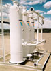
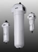
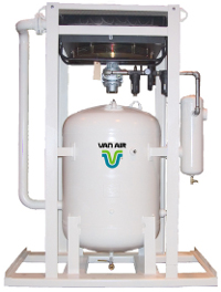
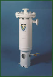
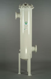
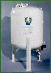
Van Air F101 Series compressed air filter housings are built to last! All F101 Series compressed air filter housings are built of welded steel and are stamped in accordance with ASME code section VIII, Div. I. with a maximum working pressure of 250 PSIG at 225° F. All F101 compressed air filters receive a rigorous hydrostatic pressure test of 1.3 times the maximum working pressure of the vessel.
The exterior of the F101 filter housing is protected by a coating of primer and air-dried machine enamel. The interior of the housing is protected by alkyd enamel. Both of these coatings help protect against corrosion, chipping and cracking to increase the durability of the housing.
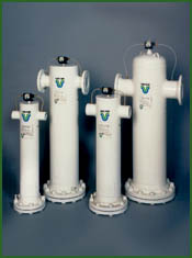
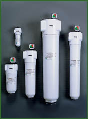
The F101 compressed air filter housings consist of six different housings, with flows ranging from 500 to 5000 SCFM at 100 PSIG. Custom units are available for flows up to 20,000 SCFM. The inlet and outlet connections of all the housings are NPT or ANSI RF flanges on a common centerline and include ports for pressure differential gauges.
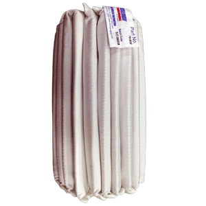
The filter element is accessible through a flange located at the bottom of the housing. All of the flanges up to 10″ in diameter are equipped with a retaining pin on one of the bolts. This permits the flange to be rotated away from the bottom of the filter housing without completely removing it from the housing assembly. Therefore, filter elements can be replaced with relative ease.
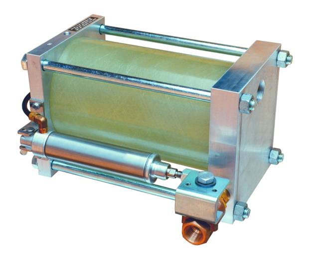
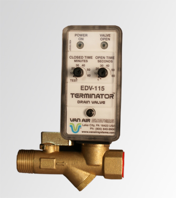
All of our F101 Series compressed air filter housings are equipped with a ball type manual drain valve. However, a Van Air automatic drain valve can be installed to automatically drain the filter housing when needed. This prevents the filter from flooding and which could cause damage to the filter element or contaminate the air system.
SELECTING A FILTER
To select the appropriate filter, determine the following conditions regarding the filter installation site:
- Maximum flow rate
- Min. and Max. operating pressures
- Operating temperature
- Pipe size
- Degree of filtration desired
- Contaminants to be removed
Next, refer to the Flow Capacities chart below and locate the column with your lowest operating pressure. Then find the flow rate closest to, but greater than, that of your system. Finally, read across to the left-hand column to determine the filter model that will meet your needs.
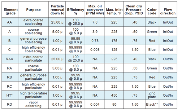
You will now need to refer to the Filtration Grades chart, also located below. Determine the element grade that meets your needs. Be sure that the maximum inlet temperature listed on the chart is sufficient for your operating conditions.
Refer to the Dimensions and Specifications chart and locate the proper filter model number. Once you have located the model number within the chart, verfiy that the inlet and outlet connections are suitable for your piping. Also make sure that there will be adequate clearance for element replacement.