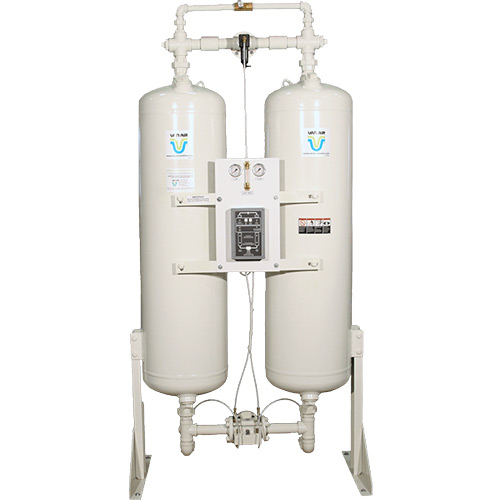
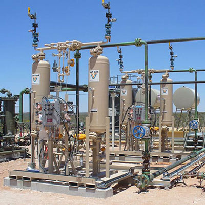
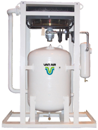
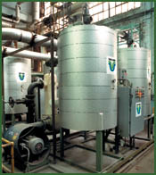
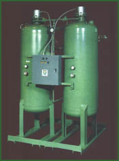
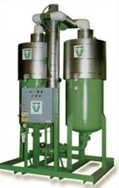
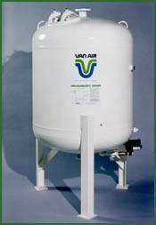
When reliable, high purity compressed air is essential, turn to HL series heatless compressed air dryers from Van Air Systems. HL series dryers have been engineered to deliver instrument quality, -40ºF pressure dew point compressed air with unparalleled dependability.
At the heart of every HL series dryer is a patented Interlock Logic 3-way inlet transfer valve. Tested to more than 1 million cycles, every movement of the valve is pneumatically interlocked, guaranteeing precise tower sequencing every time. The
interlocked valve sequencing protects your compressed air system from premature loss of flow or pressure – each phase of the drying cycle must be completed before the next can begin. This ensures uninterrupted air flow at constant pressure for your downstream equipment.
Every HL series dryer sized for 200 – 2000 SCFM comes standard with the robust solid state Touchpad Controller. The Touchpad Controller includes a cycle hold feature for preserving purge air when the compressor unloads. The Cycle Saver and more advanced EMCON II energy saving controllers are also available as options on models HL-200 through HL-2000.
Extremely Dry Compressed Air for 200 - 2000 SCFM
- 200 through 2,000 SCFM
- -40° F or -100° F pressure dew point
- Interlock Logic Sequencing
- ASME Code vessels
- Reliable
- Simple
- Long service life
Models HL-200 through HL-2000 deliver a low -40° F dew point to protect pneumatic equipment and processes from the harmful and costly effects of compressed air moisture. For even greater protection, these models offer the flexibility of switching to a -100° F dew point when needed. The cycle hold feature preserves system pressure, conserves purge air and saves energy by automatically closing the purge exhaust valve when the compressor unloads or is on standby. It resumes the cycle when compressor flow returns. The cycle monitor also features a membrane panel housed in a NEMA 4X enclosure which clearly displays dryer operation with LED indicators for each step in the cycle sequence.
- Status Indicator LEDs
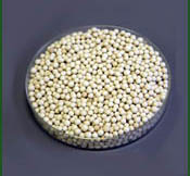
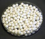
- Activated Alumina Desiccant
- Control Air Filter
- Enamel exterior finish with primer on towers, piping and supports
- NEMA 4X control enclosure
- 115V/1PH/50-60HZ supply power
- Cycle monitor (FTS) LED and contact
- Touchpad Controller
- Dryer “Hold” Feature
- -40° F dew point, adjustable for -100° F dew point
- Permanently lubricated inlet transfer valve
- Purge exhaust muffler
- Removable stainless steel desiccant diffusers
- Tower pressure gauges
- Welded steel vessels (models 120 and 150 are to ASME code)
- 230V/1PH/50-60HZ supply power
- Mounted Filters
- Mounted Filters with three-valve bypass
- Digital dew point meter with alarm contact and recorder output

Model A B C D E F Inlet / Outlet Desiccant Weight per Tower Total Weight HLS-50 65 19 20 6 63 4 1/2″ NPT 31 230 HLS-80 86 19 20 6 84 7 1″ NPT 44 280 HLS-120 76 25 20 6 75 8 1″ NPT 68 385 HLS-150 86 25 20 6 85 8 1″ NPT 83 445 For total desiccant weight, multiply by two.
Due to continuous improvement, dimensions, and specifications may change without notice.
Request certified drawing for pre-piping.
Model 60 PSIG 75 PSIG 90 PSIG 100 PSIG 125 PSIG 150 PSIG HLS-55 36 43 50 55 61 66 HLS-80 52 63 73 80 88 96 HLS-120 78 94 110 120 132 144 HLS-150 98 117 137 150 166 180 Maximum SCFM capacities at -40° F Dew Point are based on 100 PSIG, 100° F inlet temperature and 100% RH. Correction Factors
Multiply maximum capacity by .9 for 110° F, .8 for 120° F, .8 for -100° F dew point (4 minute NEMA cycle)
Operating Conditions Minimum Maximum Pressure 60 PSIG 150 PSIG Inlet Air Temp 40° F 120° F Maximum 40° F 120° F Maximum SCFM capacities at -40° F Dew Point are based on 100 PSIG, 100° F inlet temperature and 100% RH.
Model Pre-Filter After-Filter HLS-55 F200-55-1/2-C-AD F200-55-1/2-RB HLS-80 F200-85-3/4-C-AD F200-85-3/4-RB HLS-120 F200-150-1-C-AD F200-150-1-RB HLS-150 F200-150-1-C-AD F200-150-1-RB Regenerative dryers must have clean, oil-free inlet air. Lubricated Compressors – Dryer must be equipped with proper Van Air pre-filters. These filters must be drained and maintained as specified. Desiccant beds should be checked periodically and replaced if contamination has occurred. Failure to do so may result in hazardous operating conditions and will void the warranty. An after-filter should be installed downstream of the dryer to prevent desiccant particle migration.
Non-lubricated Compressors – A particulate or coalescing pre-filter is recommended to prevent pipe scale and dust from fouling the dryer. An after-filter should be installed downstream of the dryer to prevent desiccant particle migration.

