
Application
Large high speed rotation equipment such as gas turbines, steam turbines, axial and centrifugal compressors, requires a large volume of oil for lubrication, cooling, and sealing of the bearings. The lubricating oil can be either mineral based or synthetic.
Turbines are widely found throughout the world used in a variety of mechanical drive applications, including compressors, electric generators, marine propulsion, pumps and other loads. These applications are typically found in air separation, power generating, gas transmission and petrochemical facilities.
The bearing surfaces that the oil comes in contact with are very hot (350° – 700°F), and are rotating at high speeds. The high temperature and shearing action generates a large volume of very fine oil mist (droplets) plus a considerable amount of vapor (gas). When this oil mist and oil vapor is vented from the lube oil tank, it causes a visible plume. This oil plume is subject to increasingly stringent environmental laws and regulations at all government levels throughout the United States and the world.
Lube Oil Systems
The emissions from the vent of a lube oil tank are difficult to eliminate because the majority of oil mist droplets fall in the range of less than 1 micron in diameter. Oil mist control technologies that have been used in the past include electrostatic precipitators (ESPs), rotating drums, packed fiber beds and mesh pads. The manufacturers of these technologies all claim at lest 95% efficiency, some even go as high as 99% efficiency.
While all of these types of technologies are satisfactory for removing large droplets of oil, they are not adequate enough for removing sub-micron particles 0.5 microns and smaller.
Typical Lube Oil System – The primary parts of a lube oil system are as follows:
The basic operation of a lube oil system is similar for all designs. Lubricating oil (mineral or synthetic) is pumped to the bearings to lubricate and cool the metal to metal surface contacts. The high speed shearing and heat that occurs at the metal to metal contact causes droplet formation and vaporization of some of the oil.
Therefore, the return lines to the lube oil reservoir contain not only hot oil but also mist-laden air and vapor. On the return trip to the reservoir, most of the vapor cools and condenses back into oil droplets. Our detailed field and laboratory research have shown that these droplets are extremely small – between 0.05 and 0.5 microns. (See table below of particle size and distribution).
Particle Size and Distribution for Typical Turbo Machinery Lube Oil Vent
| 10 – 20% | .56 micron |
| 10 – 15% | .28 micron |
| 25 – 30% | .14 micron |
| 40 – 50% | ‹.07 micron |
The large droplets (>1 micron) drop out on the return to the reservoir. Vapor created by the high temperature at the bearing recondenses into submicronic droplets.
Once back in the reservoir, most of the larger droplets fall out; however the reservoir must be vented or open to atmosphere. This is accomplished by two means:
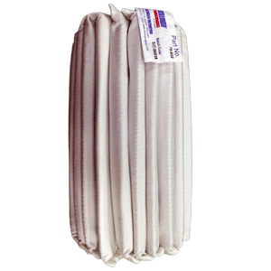
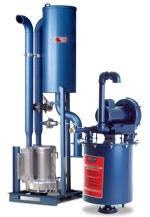
How Coalescers Work – At the heart of the Dollinger Oil Must Eliminator is a high efficiency coalescing element. Coalescers combine small aerosols through the filter media to form large droplets. The droplets recombine until their mass is significant enough to gravity-drain away from the element to a sump area.